ThermalCapture 2.0 INS Upgrade – Getting Started
On this page you can find all you need for getting started with our ThermalCapture 2.0 INS upgrade package.
In order to correctly parse recorded data, please make sure that you are using the latest version of ThermoViewer.
Preparations
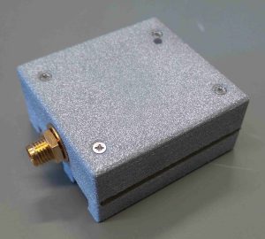
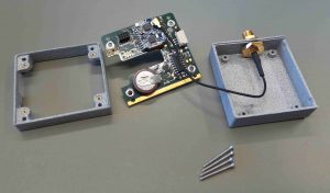
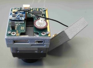
- The hardware will arrive like this:
- Remove the four screws to separate the housing parts from the PCB.
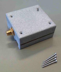
- As the result, you will have a spacer ring (left) the PCB (middle) and the top housing with the SMA antenna connector (right). Please note, that the SMA antenna connector and PCB are connected via a short wire, so please be careful while disassembling the two parts.
- Remove the back cover of your ThermalCapture 2.0 system to facilitate mounting of the INS add-on.
Assembly
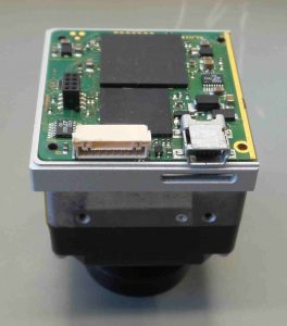
- Place the spacer ring on top of the ThermalCapture 2.0 module.
- Place the INS PCB on top of the assembly. Make sure that the 8-pin connectors from the ThermalCapture 2.0 PCB and the INS PCB match.
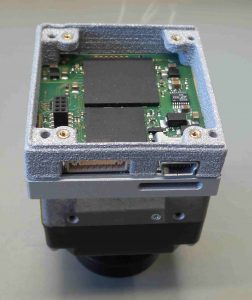
- Use the 4x M1.6 x 20 screws to fix the current assembly. Use the outer 4 holes for this step.
- Place the top cover onto the current assembly and use the 4x M1.6 x 14 screws to finish assembly.
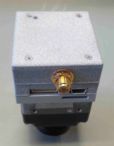
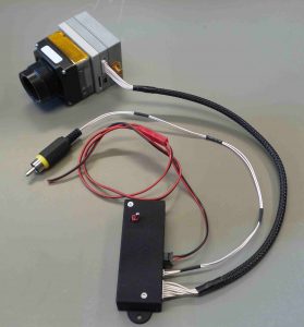
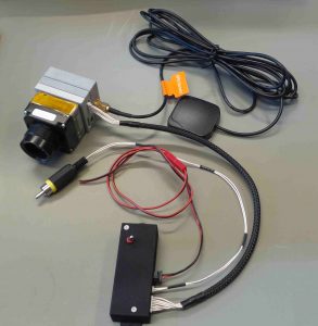
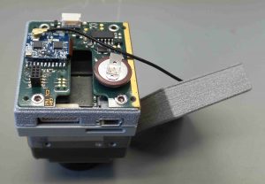
- After connecting the GPS antenna and ThermalCapture 2.0 cabling, the final setup looks like this: